




 English

Custom CNC Machining helps manufacturers turn designs into functional metal parts from first prototypes to repeated production runs. For product developers and OEM buyers, the aim is not just to make a part that looks like a CAD model. It is to create a part that works well, can be made the same way every time, and gives the best mix of quality, price, and time to make.
Whether you need a prototype, a group for testing, or regular orders of custom CNC machined metal parts, a good manufacturing process can lower design risks and make moving to full production easier.
This guide explains the steps of custom CNC machining, including making prototypes, designing and making the part, picking the Materials, checking quality, and planning for production.
1. What Is Custom CNC Machining?
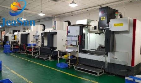
Basic machining services include CNC milling for surfaces, grooves, hollow areas, and detailed shapes; CNC turning for parts like rods, bushings, and threaded pieces; multi‑axis machining for parts with many sides and complex parts; plus drilling and threading to make holes and internal threads that are ready to put together. Other finishing options like removing edges, adding a coating, plating, or making the surface smooth are also available.
This process is used in Industries like factory machines, cars, robots, electrical parts, and automation. Common results include aluminum boxes, stainless steel supports, precise rods, mounting boards, and special mechanical parts. No special molds are needed, which means it works well for testing changes to designs and flexible small to medium production runs.
2. Stage One: Turning an Initial Design into a CNC Prototype
Prototype development starts the part of any custom CNC machining project. It allows engineers to check geometry, how parts fit together, how they work, and how easy they are to make before spending money on making a lot of them.
2.1 Define the Purpose of the Prototype
Make sure to know what you want to test before you start making the prototype. Different tests need materials, ways to finish the surface, how accurate the parts need to be, and how to check them. A model that looks checks size, shape, and how it looks. A model that works checks how well it fits, moves, and acts mechanically. A model made with the metal as the final product shows how the real part will behave. An engineering model checks sizes, threads, parts that fit together, and how it works. When testing needs to be like the product, using the same material and main production features gives better test results.
2.2 Prepare CAD Models and Engineering Drawings
3D CAD files show the shape of the part, while 2D engineering drawings explain how to make and check it. A full set of documents includes overall size, important tolerances, hole and thread details, reference points, material type, how smooth the surface needs to be, any coatings, and notes about important parts. Make sure the CAD model. The drawings are the same version. If they are not, it causes work mistakes in making and delays.
2.3 Use Prototype Results to Improve the Design
The first version of a prototype often shows hidden problems in the design: parts that're hard to reach, walls that are too thin, or tolerances that are too tight and make machining harder. Write down these issues. Decide on changes before making more. A good prototype is a step, but it does not always mean that making more parts will be easy and cheap.
3. Stage Two: Design for Manufacturability (DFM)
Design for Manufacturability, or DFM, is the process of looking at part designs to make production easier while keeping the part’s job.
DFM helps a lot with custom CNC metal parts because small changes can make a difference in how easy it is to cut, hold the part, check it, how long it takes, and how much it costs.
3.1 Simplify Redundant Features
Areas, narrow slots, complicated shapes, and parts that are hard to reach often need special tools or extra steps.
If it is allowed, make the design simpler. Remove parts that make it harder without helping the part work better. For example, a deep hole can be made shallower and inside corners can be changed to fit regular cutting tools.
3.2 Optimize Wall Thickness
Parts with walls can bend because of the pressure from cutting and holding them. This is a problem with light aluminum covers, boxes, and brackets.
The right thickness depends on the material, the shape of the part, how it will be made, and what it needs to do. There is no one-size-fits-all thickness for all CNC parts. If thin walls are needed, check how strong they are, how to make them, how to hold them, and how to check them before starting.
3.3 Set Realistic Tolerances
Tight tolerances are needed for places where parts fit together, for surfaces that must be smooth, for holes that need to be exact, and for parts that must line up. Making every part very tight adds cost and time.
Find the parts that really need to be set to tolerances based on how they fit, how they will be used, and industry rules.
3.4 Evaluate Tool. Workholding
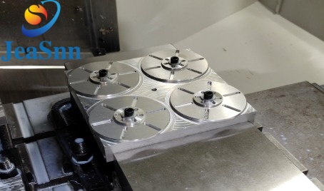
Every part that is cut must be reachable by the tools. The part must be held firmly during the process. Parts with features on sides need more setups or machines that can move in many directions. Parts that do not have areas to hold them might need special tools and a good plan for making them. Talking about these things early helps prevent problems before making starts.
4. Stage Three: Select the Right Material for Custom Metal Parts
Your choice of material directly impacts a part’s strength, corrosion resistance, weight, machinability, surface quality, and overall cost. The optimal grade is determined by the component’s operating conditions and functional requirements.
Common options include:
Aluminum 6061 – Easy-to-machine, lightweight and multipurpose, a top choice for housings, brackets and mounting plates.
Aluminum 7075 – Excellent strength-to-weight ratio for high-performance structural parts.
304 Stainless Steel – General corrosion resistance for industrial fittings and machinery hardware.
316 Stainless Steel – Reliable corrosion protection for components exposed to moisture and chemicals.
Brass – Great machinability, commonly used on connectors, fittings and precision hardware.
Carbon & Alloy Steel – Heat-treatable to meet varied requirements, suited for load-bearing parts including shafts.
Engineering Plastics – Lightweight, with good electrical insulation and chemical resistance for insulators, guides and wear parts.
Important: Varied grades in the same material family have different performance. Specify exact grades instead of generic material names. Stock availability, bar sizes, process compatibility, and certification needs should also be considered. Early material confirmation avoids redesign risks and supports precise pricing for your custom CNC machined components.
5. Stage Four: Choose the Appropriate CNC Machining Process
The ideal machining route is determined by part geometry tolerance demands, order volume, and the features to be produced.
CNC milling works for prismatic parts with flat faces, cavities, slots, holes, and intricate contours such as custom brackets, enclosures, and base plates. 3-Axis milling handles features accessible from one direction while 4-axis or 5-axis machining suits parts with surfaces or features spread across several sides.
CNC turning is the go-to process for workpieces including shafts, pins, bushings, sleeves, and threaded rotary parts. Hybrid turn-milling operations can cut handling steps. Boost efficiency for components combining rotational and milled features.
Multi-axis machining reaches -sided features and cuts re-clamping times. Still higher-end processes are not always cost-effective. Our team evaluates programming workload, fixturing, cycle time, and inspection needs to select the workflow. Prototyping prioritizes flexibility, whereas batch production focuses on repeatability, cycle efficiency, and stable fixturing performance.
6. Stage Five: Validate the Prototype Through Inspection and Testing
Prior to launching production, custom CNC prototypes must be validated to ensure compliance with approved drawings and functional specifications.
6.1 Dimensional Inspection
Dimensional verification ensures all critical characteristics stay within tolerance bands. We deploy inspection instruments matched to each feature and accuracy requirement, such as calipers, micrometers, bore gauges, height gauges, optical comparators, and coordinate measuring machines (CMMs).
6.2 Functional Testing
Dimensionally qualified parts may encounter failures during assembly or service, which is why functional prototype testing is indispensable. Test scopes are customized based on use cases covering mating thread engagement, motion clearance, load-bearing capability, sealing performance, surface quality, and visual appearance. Tests are selected according to the part’s function instead of adopting a one-size-fits-all checklist.
6.3 Document and Evaluate Outcomes
All inspection data, assembly problems, and design revisions need to be documented. When a prototype fails testing, we trace root causes to distinguish issues stemming from design, material, machining, surface finishing, or measurement error. All critical defects must be. Drawing updates must be formally approved before proceeding to the subsequent manufacturing stage.
7. Stage Six: Move from Prototype to Production-Ready Parts
Scaling from prototypes to production components involves far more than raising order volumes. The entire manufacturing workflow must be stabilized to deliver compliant results across batches and repeated production cycles.
7.1 Finalize Design Revisions
Prior to production release, confirm and freeze approved CAD data, engineering drawings, raw material specifications, surface treatment requirements, and acceptance standards. All adjustments validated through prototype qualification testing shall be incorporated into controlled release documentation to eliminate the risk of machining against obsolete designs or non-conforming unauthorized changes.
7.2 Build a Manufacturing Workflow
A production-ready machining plan outlines core operations, fixturing strategy, tooling list, machining sequence, and inspection routines. Standardized setups and locked CNC programs for recurring orders minimize batch-to-batch deviation, removing reliance on ad-hoc tweaks used during prototyping.
7.3 Arrange Pilot Runs, as Needed
A small test batch helps make sure the process works properly before making a lot of parts. It looks at things like whether the parts are all the same size, whether the tools work the same each time, whether the finish stays the same, how much the tools wear down, how the checking process works, and how the parts are packed. Test runs are not always needed. They are suggested for complicated, risky, or big orders where mistakes could be very costly.
7.4 Make Sure Production Quality Standards Are Clear
For orders that happen again, agree on what will be checked and what paperwork is needed in the beginning. This might include reports from the part-made records of measurements, proof that the materials are correct, and plans for checking some parts. Clear rules about what's acceptable help both the people buying the parts and the people making them understand what is expected.
8. Why Pick a Custom CNC Machining Partner?
A good CNC machining company does more than just make parts. Working together helps find possible problems with the design, makes sure the materials and size limits are clear, and helps plan the steps from making a model to making a regular batch of parts.
Things to look at when choosing a supplier include their experience with the materials and parts, their ability to do milling and turning work, help with checking designs before making them, the quality of their checking tools and papers, how fast they respond to changes in the model, and how much they can make.
Email:engineer@cncpartschina.com
Our team at CNCPartschina.com makes custom metal parts for machines. Whether you need aluminum boxes, stainless steel pieces, exact shafts, bushings, or brackets, giving details about the design is the first step in getting a solution that fits your needs.